Color and Attribute Micromaps

Color and Attribute Micromaps
Abstract
The hardware accelerated ray-tracing pipeline presents many opportunities to implement more advanced rendering algorithms than earlier rasterization based approaches. However, one particular aspect of the pipeline still remains a bit too costly to use in practice: The AnyHit-shader. Opacity Micromaps were introduced to alleviate this issue, but the central problem of calling arbitrary shader code on an unknown number of primitives remains prohibitively expensive. Thus, in this paper we take the first step of addressing this by further extending the concept of micromaps to arbitrary attributes; thereby theoretically giving the ray-tracing pipeline access to more generalized types of data. For this work, we focus on shading attributes, such as color, normal, metalness and roughness data, showcasing how their quality changes in a micromap-based setting, and what unique aspects they bring to the ray-tracing pipeline. Finally, we investigate how this could be used in existing shaders, and to implement various fixed-function operations during ray traversal that typically require the use of AnyHit-shaders.
1 Introduction
Ever since image texture were originally proposed by Catmull (Catmull, 1974) they have been used to great effect to improve the quality of rendered images. At first, they were applied directly on surfaces, but were later extended with per-primitive texture coordinates to improve its flexibility. Eventually, textures were even used to contain more general types of attributes, such as normals, physically based rendering properties such as metalness and roughness, and even transparency values.
Handling transparency in the hardware accelerated ray-tracing pipeline is inefficient because it typically requires calling extra-shader code in one of the innermost traversal loops. This issue was alleviated with the introduction of so-called micromaps, a fully independent structure that encode a fixed set of transparency values to allow the user to systematically reduce the number of times this extra code have to be called, effectively harking back to Catmull’s original idea textures without texture coordinates. So far, this concept has only been applied on two types of attributes: The aforementioned transparency-values, and implicit micro-vertex displacements. Thus, in this paper we investigate how to fill in the gaps between these types of micromaps, and consequently extend the concept to arbitrary attributes. At the same time, we demonstrate what kind of trade-offs are made in terms of memory footprint, frame-time, and quality, and show how these new types of micromaps could be used in the future.
2 Related Work
Micromaps were originally introduced by Gruen et al (Gruen et al., 2020) to improve ray-tracing performance for transparent objects by creating fast look-ups for triangular sub-regions that are completely opaque or transparent in an effort to reduce the number of times an AnyHit-shader has to be called. This work was later incorporated in the Vulkan® and DirectX® specifications under the name of Opacity micromaps, although with a change to the ordering of the micro-triangles to follow a special space-filling curve, which is sometimes called the Bird-curve (Werness, 2022).
During this time, Fenney et al were first to present a scheme for compressing a micromap-like structure to around of the original size. However, this structure was fundamentally different from the official opacity micromap format (Fenney and Ozkan, 2023).
Further, Waldemarson et al presented a method for interpreting the official format as a tree-based structure, thus allowing it to be heavily compressed as a succinct data structure. This approach was able to achieve a typical compression ratio of between and , but in some cases to less than of the original size. As presented however, this approach was not suitable for real-time usage beyond 3 or 4 subdivision levels due to the high look-up cost (Waldemarson and Doggett, 2024).
Moreover, the concept of displacement micromaps was added to Vulkan® as a provisional extension to render a specific representation of highly compressed and dense triangle meshes by allowing each triangle to displace individual and implicitly created micro-vertices (Werness, 2023), the construction of which was covered by Maggiordomo et al (Maggiordomo et al., 2023). However, it would appear that this particular extension has now been deprecated, and can no longer be used (NVIDIA GameWorks, 2025).
Finally, the concept of storing micromaps and associated metadata for general attributes such as colors or normals has been specified as a glTF extension (Bickford, 2023), but in this paper we describe in detail how such micromaps can be used in a rendering engine as well as what the trade-offs are made in terms of memory footprint, frame-time, and quality.
3 Background
Conceptually, an opacity micromap is simply a linear array of 1 or 2 bit values used to encode 2 or 4 fixed opacity values on implicitly created micro-triangles as described in table 1. These values then in turn allow the ray-tracing pipeline to avoid calling the expensive AnyHit-shader for all but the unknown cases (Waldemarson and Doggett, 2024).
| 2-State | 4-State | ||||||||||||
|
|
However, in contrast to opacity micromaps which are defined for micro-triangle faces, displacement micromaps operate on micro-triangle vertices. Thus, generalized micromaps need to be able to use either of these versions. In either case, micromaps can be viewed as an implicit triangle-mesh on top of each original triangle with distinct values associated with either the micro-triangles, or the micro-vertices respectively, the organization of which we describe in further detail in Section 3.1. Additional requirements that are needed to avoid gaps and discontinuities between triangles with micromaps of different subdivision levels are described further in Section 3.2.
3.1 Micro-triangles and Micro-vertices
There are numerous ways to organize both micro-triangles and micro-vertices inside a micromap: Early approaches organized micro-triangles in a top-to-bottom stripe based way (Gruen et al., 2020), whereas the official extensions eventually settled on ordering them along a special space-filling curve, similar to the Z-order curve (Werness, 2022). As for micro-vertices: We have identified three distinct approaches to organizing them inside micromaps:
- W-Minor
-
Vertices arranged from top-to-bottom from the barycentric coordinate as inferred by Gruen et al (Gruen et al., 2020).
- U-Major
-
Arranged bottom-to-top, starting from the edge between the and barycentric coordinates, as implemented in (NVIDIA GameWorks, 2025).
- Bird
-
Arranged hierarchically in triplets along the so-called Bird-curve, as implemented in (NVIDIA GameWorks, 2025).
Each of these methods are summarized in figure 2 for subdivision levels 2 and 3.
 |
 |
 |
 |
 |
 |
| W-Minor | U-Major | Bird |
3.2 Independence and Edge Handling
Micromaps are always full independent of each other, which is natural for micro-triangle ones, but for micro-vertices two limitations arise: First, all vertices along the edges of two triangles need to be duplicated, despite technically referring to the same locations. Second, the subdivision level of any neighboring micromap should only differ by one: Otherwise, cracks may appear in those regions. This issue is most pronounced for displacement micromaps, but may also surface for general attributes as discontinuities, since the micro-vertex placement become inconsistent.
In this work, this particular issue is avoided by ensuring that all micro-vertex micromaps use the same subdivision level, but in a real application this is handled by finding and decimating the triangles along the affected edges; as shown in figure 3.


4 Rendering Attribute Micromaps
In this section we detail our primary contributions that are not directly derived from existing micromap material.
4.1 Micro-Vertex Lookup
In contrast to the Vulkan® Opacity Micromap extension (Werness, 2022), the micro-vertex based micromaps used in the Displacement Micromap extension did not include an algorithm for looking up micromap values from barycentric coordinates. However, it is possible to infer such an algorithm from the existing implementation (NVIDIA GameWorks, 2025), but to our knowledge, there is no such algorithm for the W-Minor ordering. Thus, in figure 4 we present an algorithm for finding the indices to the closest triplet of micro-vertices from the barycentric coordinates. The corresponding U-Major- and Bird-order vertex-index are omitted for brevity but can be found in the supplemental material.
Once these indices are found, the barycentric coordinates can be remapped to the intersected micro-triangle for a final interpolation step. This may be done in a number of ways, but one general approach is as follows:
-
1.
Express the triangle intersection point () with barycentric coordinates for both the primary triangle vertices (), and the intersected micro-triangle vertices ():
-
2.
As each of the micro-triangle vertices belong to the same triangle, we can express each of them with barycentric coordinates with respect to the original vertices:
-
3.
Inserting them in the original equation and gathering the terms for each of the original vertices forms matrix equation:
-
4.
Solving this system using e.g., Cramer’s method yields the remapped barycentric cooordinates for any kind of sub-triangle.
Simpler approaches based on the over-determined system that only uses two of the barycentric coordinates, or the uniform micromap tessellation pattern can also be used, but are omitted for brevity.
In summary, the following steps are taken to look-up a micro-vertex attribute:
-
1.
Find the intersected micro-triangle.
-
2.
Find the corresponding micro-vertex indices.
-
3.
Fetch the micromap attributes at these indices.
-
4.
Remap the barycentric coordinates to the micro-triangle.
-
5.
Interpolate the fetched attributes with the remapped coordinates.
4.2 GLSL Lookup
The only attribute that is readily accessible to the end-user in the ray-tracing pipeline is the triangle-local barycentric coordinates, and, through an additional extension, the triangle vertex positions111GL_EXT_ray_tracing_position_fetch. Any other type of attribute must be fetched manually using indexing based on the primitive and triangle IDs. While these positions and barycentrics are the most commonly used attributes, most shading algorithms typically require more data, and at the very least the surface normal.
Theoretically, micromaps could be extended to provide users with a convenient method for accessing arbitrary attributes in the ray-tracing pipeline, effectively performing the steps outlined in Section 4.1 using the proposed API shown in figure 5. Naturally, such a change would require extensions to GLSL, SPIR-V and Vulkan to be usable, but a start at such extensions are available in the supplemental material. For this work however, all attribute fetching is handled manually in software without additional compiler or hardware support.
4.3 Fixed-Functions
In the rasterization pipeline, a number of fixed blending functions can be used to implement various types of transparency. However, it is up to the user to ensure that objects are rendered in the correct order for this blending to look correct. In contrast, in the ray-tracing pipeline any given ray can pass through all objects that it needs to consider for blending, but extra shader code is required for this to work.
Thus, another potential use case for attribute micromaps would be to allow the ray-tracing pipeline to execute a set of fixed functions on some part of the ray-payload specified by an offset with the micromap values used as arguments, thereby avoiding the need to call shaders as a part of the traversal. Thus, with an appropriate set of these functions it would be possible to implement certain features, such as transparency, without having to call the AnyHit-shader. As an example, in figure 6, we use a component-wise max-operation on a special type of color-micromap to implement a simple version of this idea.
4.4 Mipmapping
Micro-triangle based micromaps can be interpreted as a tree-like structure. As such, it is straight-forward to derive a type of mipmap-structure for micromaps; all that is needed is a method for computing a micromap value, given the values from the 4 child nodes (Waldemarson and Doggett, 2024). As an example, for a color micromap, the corresponding mipmap can be constructed as the average color of the child nodes. This is illustrated in figure 7 along with the regular image-base mipmaps and FLIP comparisons to the original texture.
 |
 |
 |
 |
| (a) Micromap-Mipmaps | (b) Image-Mipmaps | (c) Micromap FLIP Error-maps | (d) Mipmap FLIP Error-maps |
Similar to image-based mipmaps, the additional memory requirement for storing mipmaps is roughly of the original micromap size as the series: converges to .
However, in contrast to image-based mipmaps, those associated with micromaps are always strongly connected to a triangle, thus avoiding issues such as texture bleeding in atlases.
4.4.1 Micro-Vertex Mipmapping
In contrast to micro-triangles, micro-vertices arguably do not form the same type of hierarchy, but it is still possible to define a similar structure for micro-vertices by simply using micromaps with a lower subdivision level as a mipmap in the same way.
4.4.2 Using the Mipmaps
Once created, a corresponding algorithm for finding appropriate mip-levels without accessing other vertex attributes is also required. Currently, this is only possible with the GL_EXT_ray_tracing_position_fetch extension, as we must use the vertex positions to estimate the triangle surface area. With it, the micromap level-of-detail can be computed using e.g., ray-cones as described by Akenine-Möller el al (Akenine-Möller et al., 2019):
-
1.
If the cone-spread area () exceeds the triangle area (), use the highest available mip-level.
-
2.
Otherwise, the appropriate mip-levels is the first subdivision level where the cone-spread is greater than the micro-triangle area ():
-
3.
Finally, interpolate between the micromap values found at mip-levels: and .
This is described schematically in figure 8.

5 Results
In this work, we have created a software pipeline for evaluating the memory footprint, frame-runtime, and quality of both micro-triangle- and micro-vertex-based micromaps for colors, normals, and metallic-roughness factors to replace the original textures at subdivision levels to for the scenes described in table 2.
| Scenes | Quad | Avocado | Shoe | Flight-Helmet | Sponza | Sun-Temple |
|---|---|---|---|---|---|---|
| Instances | ||||||
| Meshes | ||||||
| Triangles | ||||||
| Textures | ||||||
| Opacity Micromaps | ||||||
| Special Indices (Opacity) | ||||||
| Micro-Triangle Color Micromaps | ||||||
| Micro-Triangle Normal Micromaps | ||||||
| Micro-Triangle Metal/Roughness Micromaps | ||||||
| Micro-Vertex Color Micromaps | ||||||
| Micro-Vertex Normal Micromaps | ||||||
| Micro-Vertex Metal/Roughness Micromaps |
5.1 Construction and Footprints
Each micro-triangle-based micromap is constructed by averaging the pixels covered by each sub-triangle projected onto each of the textures. Similarly, each micro-vertex-based micromap is created by performing bilinear sampling at each projected micro-vertex location. Once constructed, the total uncompressed memory footprint of the original textures and the resulting micromaps are recorded for each subdivision level, as is shown in figure 9.
| Quad | Avocado | Shoe |
 |
 |
 |
| Flight-Helmet | Sponza | Sun-Temple |
 |
 |
 |
5.2 Rendering Frame-time and Quality
Each scene is rendered on an NVIDIA GeForce RTX 3060 at with a small set of point-lights in single-bounce ray-tracer, shading all surfaces with the Trowbridge-Reitz (GGX) (Trowbridge and Reitz, 1975; Walter et al., 2007) BRDF model, once with the original textures, and then again for the micro-triangle- and the micro-vertex-based micromaps ones respectively, at each subdivision level.
The frame-time of each render is estimated by averaging the start- to end-of-pipe time as reported by the Vulkan pipeline querying API over many frames, as can be seen in figure 10.
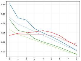
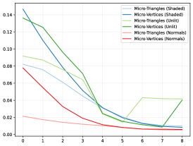
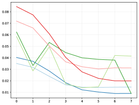
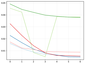
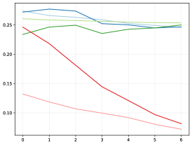
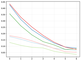
Each micromap render is compared to the corresponding texture-based rendering with the FLIP image metric (Andersson et al., 2020), as seen in table 3. Plots of the mean FLIP value can be seen in figure 11.
Additional renders with accompanying error maps that uses an Unlit shading model (i.e., base color with ambient occlusion) and world-space normal visualization and can be found in the supplemental material.
| Quad | Avocado | Shoe |
 |
 |
 |
| Flight-Helmet | Sponza | Sun-Temple |
 |
 |
 |
| Scene | Mode | Attribute | 0 | 1 | 2 | 3 | 4 | 5 | 6 | 7 | 8 | Reference |
|---|---|---|---|---|---|---|---|---|---|---|---|---|
| Quad | Shaded | Face |
|
|
|
|
|
|
|
|
|
|
| FLIP |
|
|
|
|
|
|
|
|
|
|||
| Vertex |
|
|
|
|
|
|
|
|
|
|
||
| FLIP |
|
|
|
|
|
|
|
|
|
|||
| Avocado | Shaded | Face |
|
|
|
|
|
|
|
|
|
|
| FLIP |
|
|
|
|
|
|
|
|
|
|||
| Vertex |
|
|
|
|
|
|
|
|
|
|
||
| FLIP |
|
|
|
|
|
|
|
|
|
|||
| Shoe | Shaded | Face |
|
|
|
|
|
|
|
|
|
|
| FLIP |
|
|
|
|
|
|
|
|
||||
| Vertex |
|
|
|
|
|
|
|
|
|
|||
| FLIP |
|
|
|
|
|
|
|
|
||||
| Flight-Helmet | Shaded | Face |
|
|
|
|
|
|
|
|
||
| FLIP |
|
|
|
|
|
|
|
|||||
| Vertex |
|
|
|
|
|
|
|
|
||||
| FLIP |
|
|
|
|
|
|
|
|||||
| Sponza | Shaded | Face |
|
|
|
|
|
|
|
|
||
| FLIP |
|
|
|
|
|
|
|
|||||
| Vertex |
|
|
|
|
|
|
|
|
||||
| FLIP |
|
|
|
|
|
|
|
|||||
| Sun-Temple | Shaded | Face |
|
|
|
|
|
|
|
|
||
| FLIP |
|
|
|
|
|
|
|
|||||
| Vertex |
|
|
|
|
|
|
|
|
||||
| FLIP |
|
|
|
|
|
|
|
| Quad | Avocado | Shoe |
 |
 |
 |
| Flight-Helmet | Sponza | Sun-Temple |
 |
 |
 |
6 Discussion
In this section we discuss the potential trade-offs from using micromaps to represent general attributes.
6.1 Memory Footprints
Ideally, micromaps would be constructed as a part of the retopologizing process of high-resolution models, similar to the process suggested by Maggiordomo et al (Maggiordomo et al., 2023), rather than sampled from textures as is done in this work. However, by using existing textured assets as a base effectively turns the micromaps into downsampled versions of the textures, making it straight-forward to evaluate the quality and memory footprint. Thus, we can easily see that despite creating numerous micromaps, the total memory footprint in the scene remains consistently low for subdivision levels , which are the levels we would consider reasonable for general models. Although, in some corner cases it can be feasible to use many more subdivision levels, such as for the Quad model, which can go beyond level 8 before it reaches parity with the original textures.
6.2 Frame-time
The frame-time performance was mostly disregarded in this work as it is not possible make a fair comparison between the hardware accelerated texturing pipeline and our software implementation for looking-up attribute micromaps. However, as can be seen in figure 10, the micromap look-up algorithms are all in-line with the references for all shading methods despite this limitation. As such, it stands to reason that a hardware implementation of the look-up algorithms described in this work may actually create a noticeable improvement.
6.3 Quality
Interestingly, micromaps based on micro-triangles frequently receive a lower mean FLIP value than the corresponding micro-vertex ones at the same level, but are subjectively of worse quality due to the obvious tessellation pattern. Although, once the subdivision level is high enough, this is no longer noticeable, but at those levels, the memory footprints become a real concern.
It appears as if micro-vertex micromaps are particularly suitable for assets with a dense vertex distribution, as can be seen clearly for the Shoe and Flight-Helmet models in figure 3: In these scenes, it is possible to get by with a very low amount of subdivision levels, typically between , without noticeably impacting the visual quality, yet only requiring between of the original texture footprint. In contrast, in models with a very sparse vertex distribution, such as in most of the Sponza scene and some parts of the Sun-Temple scenes, these types of micromaps cannot be used in practice due to the high subdivision level needed to reach an acceptable quality. The same issue can also be seen in figure 1 along the tongue of the shoe where the texture detail is high, but vertex density is relatively low, although to a much lower extent.
7 Future Work
While it appears that displacement micromap have been abandoned in favor of a more dynamic level-of-detail extension system inside the acceleration structure (Khronos Group, 2025), there are still a lot of potential use-cases for more generalized types of micromaps.
In this paper we only briefly touched upon how these generalized micromaps are actually authored: A complete system for generating and working with micromaps would need to handle a number of corner cases that was glossed over in this work. Additionally, finding algorithms to efficiently update or change micromaps during runtime and for animations may also be an interesting avenue of research.
One major limitation with the micromap format, is the lack of dedicated design software that support them: Existing image textures can easily be modified in any number of image-editors, but micromaps are limited to be generated from a handful of specialized tools. Thus, adding support for visualizing the underlying micromap-meshes, or even painting or editing individual micro-primitive values could prove very useful.
Interestingly, given that micromaps can be defined for both micro-triangles and micro-vertices, it stands to reason that one can create micromaps to store data for other aspects of the triangle as well, e.g., the micro-edges. This may be practical for some things, such as marking sharp edges, although, it remains to be seen if something like that is useful in practice.
Furthermore, given the more generalized data stored in these micromaps, it would make sense to invent a new scheme for compressing and looking up the attribute data; as approaches for compressing vertex attributes may be applicable. Additionally, in this work we did not use special-indices for anything besides opacity micromaps. It is possible that something similar could be used for general micromaps, e.g., to use a fixed palette of color values.
Moreover, several rendering algorithms can operate directly on bare barycentric coordinates; such as the recently presented “Surface-Stable Fractal Dithering” (Johansen, 2025), as such, it may be possible to directly replace these algorithms with appropriate micromaps, particularly if coupled with appropriate micromap mipmapping hierarchies.
8 Conclusions
In this paper we have presented micromaps with more generalized attributes, such as colors and normals, with all the necessary algorithms needed for them to be used as shading primitives in a rendering engine, allowing them to be used in place of the corresponding textures. Thus allowing assets with dense vertex distributions to use micromaps to substantially reduce the memory footprint with a minimal loss of quality, and no perceptible loss of frame-time performance; even without proper hardware acceleration.
We also further extend the micromaps concept with an analogue to texture mipmapping, a GLSL API proposal to make accessing micromap values more convenient in ray-tracing shaders, and show how micromaps can be used for fixed-function blending in the ray-tracing pipeline, allowing the implementation of effects such as partial transparency without the need for AnyHit-shaders.
9 Acknowledgments
This work was partially supported by the Wallenberg AI, Autonomous Systems and Software Program (WASP) funded by the Knut and Alice Wallenberg Foundation. We would also like to thank Arm Sweden AB for letting Gustaf pursue a PhD as one of their employees. Additionally, we would like to thank Rikard Olajos for his valuable input during this work. Finally, we are very grateful for the extensive input from our reviewers that helped us identify some areas that needed a bit of extra work.
References
- Texture level of detail strategies for real-time ray tracing: high-quality and real-time rendering with dxr and other apis. pp. 321–345. External Links: ISBN 978-1-4842-4426-5, Document Cited by: §4.4.2.
- FLIP: A Difference Evaluator for Alternating Images. Proceedings of the ACM on Computer Graphics and Interactive Techniques 3 (2), pp. 15:1–15:23. External Links: Document Cited by: §5.2.
- Nvidia Inc.. External Links: Link Cited by: §2.
- A subdivision algorithm for computer display of curved surfaces.. Ph.D. Thesis, The University of Utah, The University of Utah. Note: AAI7504786 Cited by: §1.
- Compressed Opacity Maps for Ray Tracing. In High-Performance Graphics - Symposium Papers, J. Bikker and C. Gribble (Eds.), EUROGRAPHICS Association Groene Loper 3, 5612AE Eindhoven, pp. 23–31. External Links: ISSN 2079-8687, ISBN 978-3-03868-229-5, Document Cited by: §2.
- CryTek sponza. Note: https://www.cryengine.com/asset-db/product/crytek/sponza-sample-scene Cited by: Table 2.
- Unreal engine sun temple, open research content archive (orca). Note: http://developer.nvidia.com/orca/epic-games-sun-temple External Links: Link Cited by: Table 2.
- Sub-triangle opacity masks for faster ray tracing of transparent objects. Proc. ACM Comput. Graph. Interact. Tech. 3 (2). External Links: Link, Document Cited by: §2, item W-Minor, §3.1.
- Flight-helmet model. The Khronos Group Inc., The Khronos Group Inc.. Note: https://github.com/KhronosGroup/glTF-Sample-Assets/tree/main/Models/FlightHelmetAccessed: 2025-04-04. This model is converted from Maya by Gary Hsu (2018) and is licenced under CC0 1.0 Universal. External Links: Link Cited by: Table 2.
- Dither3D. Note: Accessed: 2025-03-06 External Links: Link Cited by: §7.
- VK_NV_cluster_acceleration_structure - vulkan extension specification. Note: Accessed: 2025-03-06 External Links: Link Cited by: §7.
- San miguel. Note: https://www.pbrt.org/scenes-v3/ Cited by: Table 2.
- Micro-mesh construction. ACM Trans. Graph. 42 (4). External Links: ISSN 0730-0301, Link, Document Cited by: §2, §6.1.
- Avocado model. The Khronos Group Inc., The Khronos Group Inc.. Note: https://github.com/KhronosGroup/glTF-Sample-Assets/tree/main/Models/AvocadoAccessed: 2025-04-04. This model is provided by Microsoft (2017) and is licenced under CC0 1.0 Universal. External Links: Link Cited by: Table 2.
- Displacement micromap toolkit. Note: Accessed: 2025-03-06 External Links: Link Cited by: §2, item U-Major, item Bird, §4.1.
- MaterialVariantsShoe model. The Khronos Group Inc., The Khronos Group Inc.. Note: https://github.com/KhronosGroup/glTF-Sample-Assets/tree/main/Models/MaterialsVariantsShoeAccessed: 2025-04-04. This model is provided by Shopify (2021) and is licenced under CC BY 4.0 International. External Links: Link Cited by: Table 2.
- Average irregularity representation of a rough surface for ray reflection. J. Opt. Soc. Am. 65 (5), pp. 531–536. External Links: Link, Document Cited by: §5.2.
- Succinct opacity micromaps. Proc. ACM Comput. Graph. Interact. Tech. 7 (3). External Links: Link, Document Cited by: §2, §3, §4.4.
- Microfacet models for refraction through rough surfaces. In Proceedings of the 18th Eurographics Conference on Rendering Techniques, EGSR’07, Goslar, DEU, pp. 195–206. External Links: ISBN 9783905673524 Cited by: §5.2.
- The Khronos Group Inc.. External Links: Link Cited by: §2, §3.1, §4.1.
- External Links: Link Cited by: §2.
![[Uncaptioned image]](/images/attribute-micromaps/x68.png)
![[Uncaptioned image]](/images/attribute-micromaps/x69.png)
![[Uncaptioned image]](/images/attribute-micromaps/x70.png)
![[Uncaptioned image]](/images/attribute-micromaps/x71.png)
![[Uncaptioned image]](/images/attribute-micromaps/x72.png)
![[Uncaptioned image]](/images/attribute-micromaps/x73.png)